Virtual Ethernet Application Guide
Table of Contents:
Overview
The Virtual Ethernet architecture (here) supports your development phases with sample applications that include loopback paths for bringup and debug of the Virtual Ethernet application and custom CL, all the way to end-to-end application integration with live traffic.
Virtual Ethernet Application Setup and Use
The distinct phases of Virtual Ethernet Application setup and use are:
Software installation and build
System setup and device binding (e.g. FPGA and ENI)
Application setup and start
The next sections walk through the setup and usage phases including example workflows.
Example Workflows
Simple Loopback
This example maximizes PPS for 64B packets with a single vCPU using the
DPDK testpmd application to drive the DPDK SPP PMD and the FPGA SDE IP.
This may be used for streaming CL bringup and performance measurements
in an isolated loopback environment. It runs testpmd in auto-start mode,
sends the first burst of TX packets (32 packets by default), and
displays packet statistics every 3 seconds (including PPS). To exit the
example, use ctrl-c.
Software installation and build phase
cd $(SDK_DIR)/apps/virtual-ethernet/scripts
sudo ./virtual_ethernet_install.py <install_dir>
System setup and device bind phase, e.g. on instance boot
sudo fpga-load-local-image -S <fpga-slot> -I <SDE loopback CL AGFI>
cd $(SDK_DIR)/apps/virtual-ethernet/scripts
sudo ./virtual_ethernet_setup.py <install_dir>/dpdk <fpga-slot>
Testpmd application setup and start phase
cd <install_dir>/dpdk
sudo ./build/app/dpdk-testpmd -l 0-1  -- --port-topology=loop --auto-start --tx-first --stats-period=3
The testpmd application will display the number of TX-packets RX-packets sent to/from the SDE. Everything three seconds, the number of TX-packets and RX-packets will be updated to show the new packet total. In addition, the packets per second throughput is calculated and updated.
######################## NIC statistics for port 0  ########################
RX-packets: 28791397   RX-missed: 0          RX-bytes:  1842650496
RX-errors: 0
RX-nombuf:  0
TX-packets: 28791429   TX-errors: 0          TX-bytes:  1842651456

Throughput (since last show)
Rx-pps:      4798711          Rx-bps:   2456940768
Tx-pps:      4798711          Tx-bps:   2456940424
############################################################################
Please refer to Q: Where can I find DPDK testpmd feature documentation? for a quick reference guide on the supported testpmd features and the link to the full testpmd documentation.
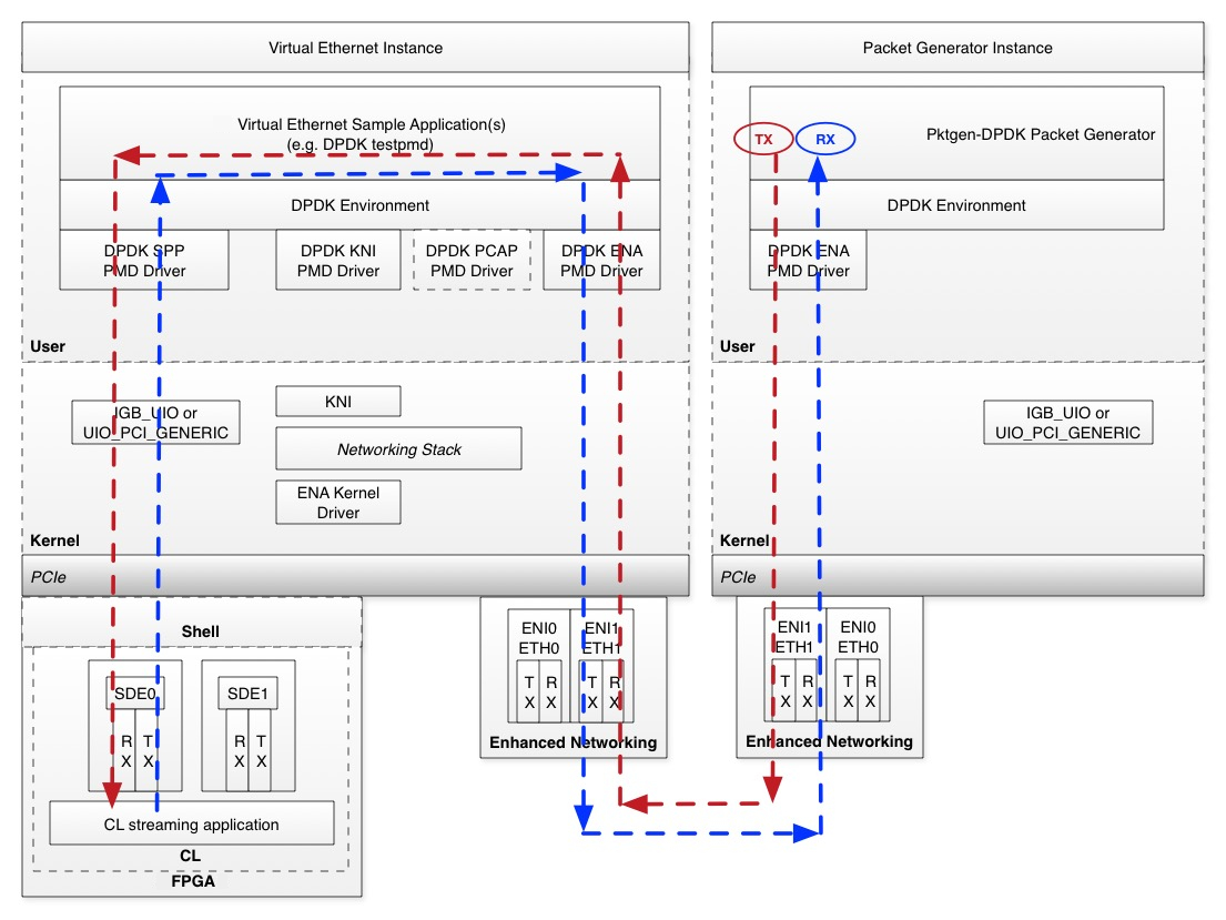
PacketGen Dual Instance Loopback
This example maximizes PPS for 64B packets with a single vCPU using two instances to test end-to-end traffic flows.
In the below diagram, the red line shows the Ethernet frame path
from the Packet Generator Instance into the CL streaming application
in the Virtual Ethernet Instance. The blue line shows the
Ethernet frame path from the CL streaming application in the Virtual
Ethernet Instance to the Packet Generator Instance. For best
performance, the Virtual Ethernet Instance and the Packet
Generator Instance should be created in the same VPC and placement
group. Please refer to Q: Why can’t I launch instance type X in a placement group with an F2? if you are unable to launch other instances with the F2 instance. It should also be an instance type
which supports the Elastic Network Adapter (driver)
type of Enhanced Networking. Please refer to Q: What instance types support Enhanced Networking? for more information. This example was tested using an
f2.48xlarge and an m5.2xlarge as the Packet Generator
Instance.
Virtual Ethernet Instance
This workflow sets up the DPDK testpmd application for port-to-port forwarding through the DPDK ENA PMD, the DPDK SPP PMD and SDE. It then runs testpmd in auto-start mode and displays packet statistics every 3 seconds (including PPS). To exit testpmd, use
ctrl-c.
Traffic Generator Instance
The Traffic Generator instance uses pktgen-dpdk to send max PPS towards the Virtual Ethernet instance. This example was tested using an
m5.2xlargeand anf2.48xlarge.
Network Interface Setup
This example workflow places the PacketGen traffic on
eth1, and reserveseth0for your SSH sessions and other control plane traffic.An additional network interface can be attached via the EC2 “Attach Network Interface” workflow. Your new
eth1network interface is automatically initialized if you are using Amazon Linux. If you are using Ubuntu, please refer to Q: How do I setup the additional ENI/eth1 interface for the PacketGen Dual Instance Loopback example?. Refer to Q: How do I retrieve the ENI DBDF for the additional ENI/eth1 interface that is used in the PacketGen Dual Instance Loopback example? to retrieve the ENIDBDF(e.g. the PCI Domain:Bus:Device.Function) for your new ENI interface.
Virtual Ethernet instance
Software installation and build phase
cd $(SDK_DIR)/apps/virtual-ethernet/scripts
sudo ./virtual_ethernet_install.py <install_dir>
System setup and device bind phase, e.g. on instance boot
sudo fpga-load-local-image -S <fpga-slot> -I <SDE loopback CL AGFI>
cd $(SDK_DIR)/apps/virtual-ethernet/scripts
sudo ./virtual_ethernet_setup.py <install_dir>/dpdk <fpga-slot> --eni_dbdf <eth1 ENI DBDF> --eni_ethdev <eth1 ENI ethdev>
Testpmd application setup and start phase
cd <install_dir>/dpdk
sudo ./build/app/dpdk-testpmd -l 0-1  -- --port-topology=chained --auto-start --stats-period=3 --forward-mode=spp-eni-addr-swap
The spp-eni-addr-swap testpmd forwarding mode swaps the Ethernet MAC
and IP addresses so the Packet Generator instance can receive the
loopback Ethernet frames.
Please refer to Q: Where can I find DPDK testpmd feature documentation? for a quick reference guide on the supported testpmd features and the link to the full testpmd documentation.
Packet Generator Instance
Software installation and build phase
cd $(SDK_DIR)/apps/virtual-ethernet/scripts
./virtual_ethernet_pktgen_install.py <install_dir>
During installation, dpdk, pktgen-dpdk, dpdk-kmods, and numactl are cloned, built, and installed in the <install_dir>. The <install_dir> will have
dpdk dpdk-kmods numactl pktgen-dpdk
System setup and device bind phase, e.g. on instance boot
cd $(SDK_DIR)/apps/virtual-ethernet/scripts
sudo ./virtual_ethernet_pktgen_setup.py <install_dir> --eni_dbdf <eth1 DBDF> --eni_ethdev <eth1 ENI ethdev>
Packet Generator setup and start phase:
A sample Packet Generator pktgen-ena.pkt script is provided. You
will need to modify it to work with your F2 instances.
cat $(SDK_DIR)/apps/virtual-ethernet/scripts/pktgen-ena.pkt
set 0 dst mac 12:DD:AB:C2:D3:B8  # set this to Virtual Ethernet instance eth1 mac address
set 0 src ip 172.31.63.86/24     # set this to the Packet Generator instance eth1 IP address
set 0 dst ip 172.31.58.142       # set this to the Virtual Ethernet instance eth1 IP address
set 0 sport 54321
set 0 dport 51234
set 0 type ipv4
set 0 proto udp
set 0 size 64
start 0
Similarly a pktgen-ena-range.pkt script is provided for multiflow
run with a range of parameters. This needs to be modified with
corresponding dest mac address, src and dest ip addresses.
cat $(SDK_DIR)/apps/virtual-ethernet/scripts/pktgen-ena-range.pkt
set 0 type ipv4
range 0 dst mac start 06:06:5c:8b:30:0d     # set this to Virtual Ethernet instance eth1 mac address
range 0 dst mac min 06:06:5c:8b:30:0d       # set this to Virtual Ethernet instance eth1 mac address
range 0 dst mac max 06:06:5c:8b:30:0d       # set this to Virtual Ethernet instance eth1 mac address
range 0 dst mac inc 00:00:00:00:00:00
range 0 src ip start 172.31.60.245          # set this to the Packet Generator instance eth1 IP address
range 0 src ip min 172.31.60.245            # set this to the Packet Generator instance eth1 IP address
range 0 src ip max 172.31.60.245            # set this to the Packet Generator instance eth1 IP address
range 0 src ip inc 0.0.0.0
range 0 dst ip start 172.31.59.180          # set this to the Virtual Ethernet instance eth1 IP address
range 0 dst ip min 172.31.59.180            # set this to the Virtual Ethernet instance eth1 IP address
range 0 dst ip max 172.31.59.180            # set this to the Virtual Ethernet instance eth1 IP address
range 0 dst ip inc 0.0.0.0
range 0 src port start 1000
range 0 src port min 1000
range 0 src port max 1020
range 0 src port inc 1
range 0 dst port start 1000
range 0 dst port min 1000
range 0 dst port max 1020
range 0 dst port inc 1
range 0 size start 4096
range 0 size min 4096
range 0 size max 4096
range 0 size inc 1
range 0 proto tcp
enable 0 range
start 0
When running the below command, with -j option, the packet size can be set to jumbo frames and try the example run with pkt size 4096
cd <install_dir>/pktgen-dpdk
sudo LD_LIBRARY_PATH=/usr/local/lib/x86_64-linux-gnu ./build/app/pktgen -l 0,1 -n 16 --proc-type auto --log-level 7 --socket-mem 4096 --file-prefix pg -- -T -j -P -m [1].0 -f $(SDK_DIR)/apps/virtual-ethernet/scripts/pktgen-ena.pkt
FAQ
Q: What is the AGFI ID for the SDE loopback CL?
The AGFI ID for the SDE loopback CL is found in the
CL_SDE Example Metadata section at the bottom of the
CL_SDE README
here.
Q: Where can I find DPDK testpmd feature documentation?
The full documentation for DPDK testpmd features is found here.
Note that not all of the DPDK testpmd features are supported by the SPP and ENI PMDs. SPP supports a limited subset of the DPDK Ethernet upper API (e.g. DPDK eth_dev_ops) to the DPDK application(s) (e.g. testpmd) for purposes of passing through streaming packets to/from the SDE.
The application examples use testpmd auto-start mode. testpmd also
supports an interactive mode that may be used during debug and test
sessions. Interactive mode is especially useful when running testpmd
within the gdb debugger. Below is a quick reference guide for some
of the supported testpmd interactive mode commands that may be used with
the application examples.
Q: Can I map multiple ENIs to a SPP?
The PacketGen Dual Instance Loopback example uses a one-to-one mapping between SPP and ENI as configured via testpmd. Your custom applications(s) may map multiple ENIs to a SPP as long as your application follows the DPDK threading model (e.g. ‘lockless’) and the CL supports Ethernet frames from multiple ENIs.
Q: Can I map different ENIs to different SPP queues?
The simple PacketGen Dual Instance Loopback example uses a one-to-one mapping between SPP and ENI as configured via testpmd. Multiple SPP queues are not yet supported.
Q: What performance should I expect?
The goal of SPP on F2 is to sustain line rate network bandwidth for all network configurations supported on the AWS FPGA instances.
Q: How does packet drop and flow control work?
Packet drop and flow control characteristics are application specific, since you are free to use the DPDK drivers and environment in the best way that suits your specific application.
As an example, let’s assume we have a packet forwarding topology that directly connects an ENI to an SPP that does not drop any remaining TX packets after partial TX packet burst has been submitted to ENI. Since the application is in control of the packet processing, it can flow off the SPP RX side by asking for fewer RX packets in the next call to the SPP RX packet burst API. If the ENI TX backpressure condition persists, the application may stop calling the SPP RX packet burst API. At this point, SPP will stop processing RX descriptors, the C2H buffer in the SDE will become full (see the SDE HW Guide here), and this will backpressure the AXI-Stream interface (e.g. the SDE will de-assert the ‘ready’ signal on the C2H AXI-Stream interface). This may then backpressure the SPP TX side, which is again under application control. If the SPP TX side backpressure condition persists, the application may stop processing ENI RX packets and this will eventually cause packet drops on the ENI RX side facing the network.
Q: How are SDE errors reported?
On each call to the SPP TX/RX packet burst APIs, the DPDK SPP PMD checks the SDE write-back TX/RX status. If the SDE write-back status is non-zero, the SPP PMD takes the following steps:
Log-info the TX/RX channel SPP driver status variables and the SDE status write-back variables
Log-info the specific SDE error info from the SDE block that encountered the error
Log-info the descriptor ring entries
Increments the TX/RX sde_error stat
Log-error and return from the TX/RX status checking method.
Return 0 packets processed from the SPP TX/RX packet burst APIs (e.g. the DPDK TX/RX packet burst APIs return a uint16_t that indicates the number of packets that were processed in the current call).
Your application should periodically check to see if the TX/RX sde_error
stat is non-zero (e.g. by calling the eth_dev_ops xstats_get API for
error checking in the slow-path). If the TX/RX sde_error stat is
non-zero, your application should take the following error recovery
steps:
Quiesce all calls to TX/RX packet burst (e.g. discontinue calling
rte_eth_dev tx/rx_pkt_burst)Release all of the SPP queues (e.g. call
eth_dev_ops tx/rx_queue_release)Remove the SPP PCI device (e.g. call
rte_pci_driver remove)Reload the AGFI using
fpga-load-local-imageto ensure the CL is fully reset
At this point, the DPDK SPP driver and SDE may be re-initialized as normal. The SDE is reset during the SPP PCI device probe initialization step, and the TX/RX queues are re-initialized during the TX/RX queue setup phase.
Q: What is the minimal packet size supported by AWS FPGA virtual ethernet IP?
FPGA CL must generate packets with 64Byte or more to meet the Ethernet minimum frame size requirement.
Q: What is the maximal packet size?
It is the maximal packet size offered by ENI on your instance (including the 4-byte CRC).
Q: Should I calculate the Ethernet frame CRC32?
No, SPP relies on the ENI to check CRC on receive and calculate it on transmit.
Q: What MAC address should I use for SPP?
The SPP MAC address is normally unused for testpmd port based forwarding and defaults to all zeroes. The default SPP MAC address may be changed if needed using the testpmd ‘mac_addr set’ command when using the testpmd application, or by your custom application using the DPDK APIs.
Note that the SPP and SDE do not perform any modifications to the TX packets (e.g. from the application to the CL), or the RX packets (e.g. from the CL to the application). The SDE does not perform any packet filtering (e.g. based on the packet destination MAC address).
Q: How many TX and RX descriptors are supported?
The number of supported TX and RX descriptors per SPP queue pair is parameterized within the SDE block and reported by the SDE to SPP via registers within the SDE block (see the SDE H2C and C2H channels here). SPP defines a minimum and the maximum number of descriptors between 64 and 32K. The number of TX and RX descriptors implemented in the SDE and requested by the DPDK application in the SPP queue setup phase must be equal, and a power of 2.
Q: How do I configure SPP to use SDE regular or compact descriptors?
The SDE may be built with regular or compact descriptor types (see the
C2H_DESC_TYPE and H2C_DESC_TYPE in the Design Parameters section
here). The SPP PMD also supports regular or
compact descriptor types at compile time via the SPP_USE_COMPACT_DESCS
define within spp_defs.h. The default descriptor type for the SDE and
SPP is regular to support the full 64-bit DMA addressing. If there
is a mismatch between the SDE and SPP descriptor type build options, the
SPP driver will log an error similar to the following:
Mismatched build options: SDE descriptor type is regular, SPP PMD
descriptor type is compact.
PMD: spp_dev_cap_get(): SDE C2H Desc Info(0x00400000), type=regular, is not supported
Mismatched build options: SDE descriptor type is compact, SPP PMD
descriptor type is regular.
PMD: spp_dev_cap_get(): SDE C2H Desc Info(0x00800001), type=compact, is not supported
Q: What operating systems are supported?
The Virtual Ethernet application is tested and supported for Linux operating systems (Amazon Linux and Ubuntu).
Q: How do I setup the additional ENI/eth1 interface for the PacketGen Dual Instance Loopback example?
An additional network interface can be attached via the EC2 “Attach
Network Interface” workflow. Your new eth1 network interface is
automatically initialized if you are using Amazon Linux. If you are
using Ubuntu, please execute the following steps:
Use the EC2 Console to view the IP Address and Mac Address of the
additional network interface. The Mac Address 12:1e:7e:0b:70:2e and
IP Address 172.1.1.22 are used for illustration purposes.
Create an eth1 specific configuration using the existing ethernet
adapter as a template.
sudo vi /ect/netplan/50-cloud-init.yaml
eth1:
      dhcp4: false
      dhcp6: false
      addresses:
      - 172.1.1.22
      match:
        macaddress: 12:1e:7e:0b:70:2e
      set-name: eth1
Initialize the eth1 interface using sudo netplan --debug apply
and then show the eth1 configuration using ifconfig.
ifup eth1
Determining IP information for eth1... done.
ifconfig eth1
eth1: flags=4163<UP,BROADCAST,RUNNING,MULTICAST>  mtu 9001
        inet 172.1.1.22  netmask 255.255.240.0  broadcast 172.1.1.255
        inet6 fe80::101e:7eff:fe0b:702e  prefixlen 64  scopeid 0x20<link>
        ether 12:1e:7e:0b:70:2e  txqueuelen 1000  (Ethernet)
        RX packets 10  bytes 1052 (1.0 KiB)
        RX errors 0  dropped 0  overruns 0  frame 0
        TX packets 12  bytes 1416 (1.3 KiB)
        TX errors 0  dropped 0 overruns 0  carrier 0  collisions 0
At this point, the eth1 interface is ready for the setup script(s)
that are described in the PacketGen Dual Instance Loopback example.
Q: How do I retrieve the ENI DBDF for the additional ENI/eth1 interface that is used in the PacketGen Dual Instance Loopback example?
The ENI DBDF for the eth1 interface can be retrieved as follows
using a grep for 1d0f:ec20 through the lspci command output.
lspci -D | grep "1d0f:ec20"
0000:00:03.0 Ethernet controller: Device 1d0f:ec20    # this is eth0
0000:00:04.0 Ethernet controller: Device 1d0f:ec20    # this is eth1.  The DBDF is 0000:00:04.0
Q: How do I update DPDK and SPP with the Vendor/Device ID for my CL?
Within <install_dir>/dpdk/drivers/net/spp there is a file called
spp_ethdev.c. Your Vendor and Device ID should be added to the
following table in spp_ethdev.c and then DPDK should be recompiled.
static const struct rte_pci_id pci_id_spp_map[] = {
        { RTE_PCI_DEVICE(PCI_VENDOR_ID_AMAZON, PCI_DEVICE_ID_SDE_LOOPBACK_CL) },
        { RTE_PCI_DEVICE(<Your Vendor ID>, <Your Device ID>) },
        { .device_id = 0 },
};
Rebuild DPDK as follows:
cd <install dir>/dpdk
ninja -C build
Within <install dir>/dpdk/usertools there is a file called
dpdk-devbind.py. Your Vendor and Device ID should be added to the
following table in dpdk-devbind.py.
aws_fpga_sde = {'Class': '05', 'Vendor': '1d0f', 'Device': 'f002',
              'SVendor': None, 'SDevice': None}
<your tag> = {'Class': '05', 'Vendor': '<Your Vendor ID>', 'Device': '<Your Device ID>',
              'SVendor': None, 'SDevice': None}

network_devices = [network_class, cavium_pkx, avp_vnic, aws_fpga_sde, <your tag>]
You should then run the virtual_ethernet_setup.py script which will
re-run the dpdk-devbind.py script to bind DPDK and SPP to your
Vendor and Device Id.
Q: What instance types support Enhanced Networking?
At the time of writing, compatible instance types are all Nitro-based
instances
and the following Xen-based instances G3, H1, I3, m4.16xlarge, P2,
P3, P3dn, R4. For more information, see the documentation on Enhanced
Networking on
Linux.
Q: Why can’t I launch instance type X in a placement group with an F2?
When you launch instances in a cluster placement group, AWS attempts to launch those instances on hardware which share high capacity networking infrastructure. It is not always possible to launch heterogeneous instance types within such a group. This depends on the underlying arrangement of this physical hardware. If it is not possible to launch an instance of the desired type in a placement group with an F2, try using another F2 instance as the packet generator instance. For more information, see the documentation on placement groups.